Troubleshooting Manual
Fault Finding Charts and Tables
The troubleshooting manuals below is an easy step by step process to fault find your Baxi Combi Boiler. For a quick and easy check conduct the following:
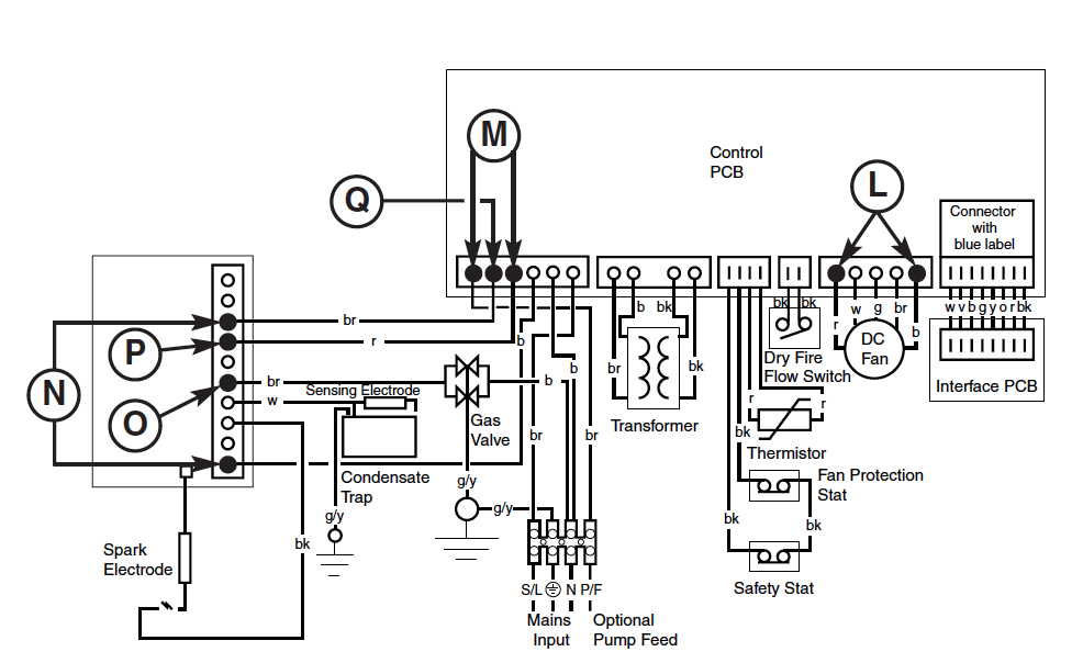
- Electrical. Analyse the electrical circuits by using a multimetre inspecting for for short circuits, earth continuity and earth resistance. Check that the system has correct polarity.
- 230V Supply. Check that your boiler has a supply voltage of 230 V.
- Gas Supply. Check your boiler has a gas supply. Ensure supply has been sufficiently purged.
Warning Warning: Ensure only qualified CORGI registered contractors do these checks, it is illegal and dangerous if you conduct your own gas checks!
- Water Filling. Inspect your boiler making sure it is full of water and has a pressure of 1-1.5 BAR. Too little water in your boiler will reduce your efficiency.
- Control. Check that your main switch is showing ‘on’
- Temperature. Check your heating temperature is set on to the maximum setting.
- External Controls. Ensure that the controls circuit thermostat is asking for heat.
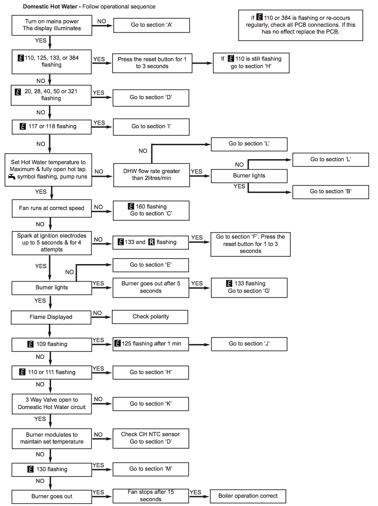
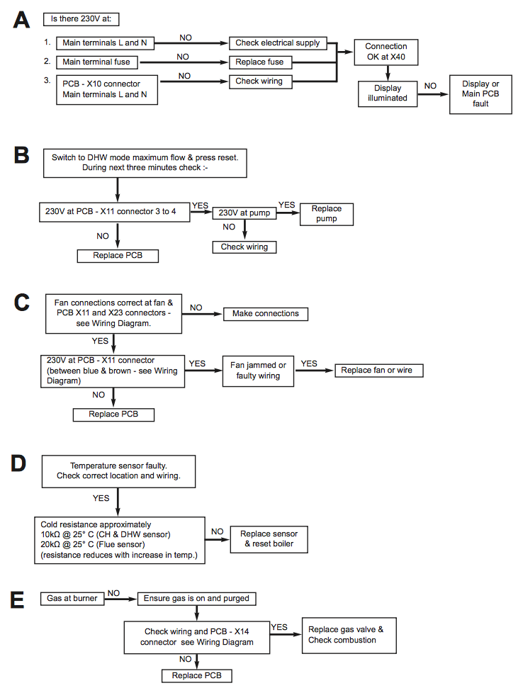
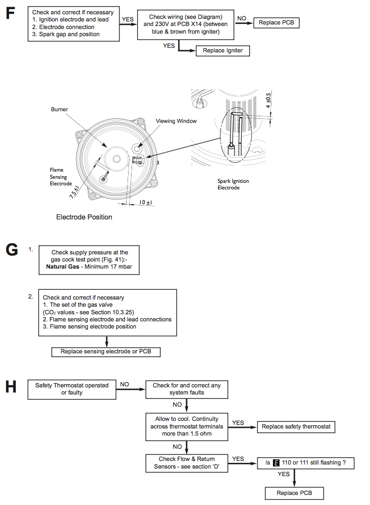
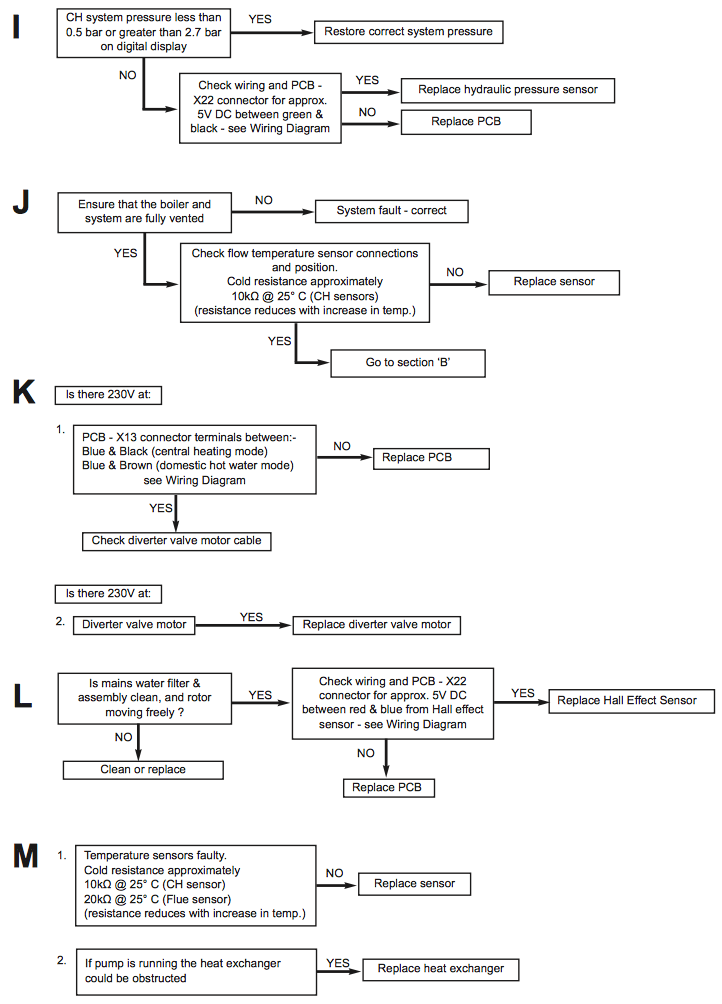
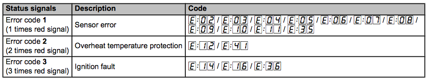
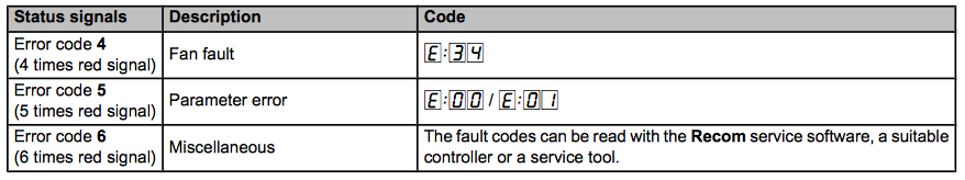
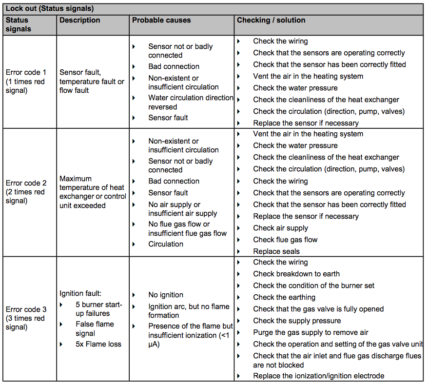
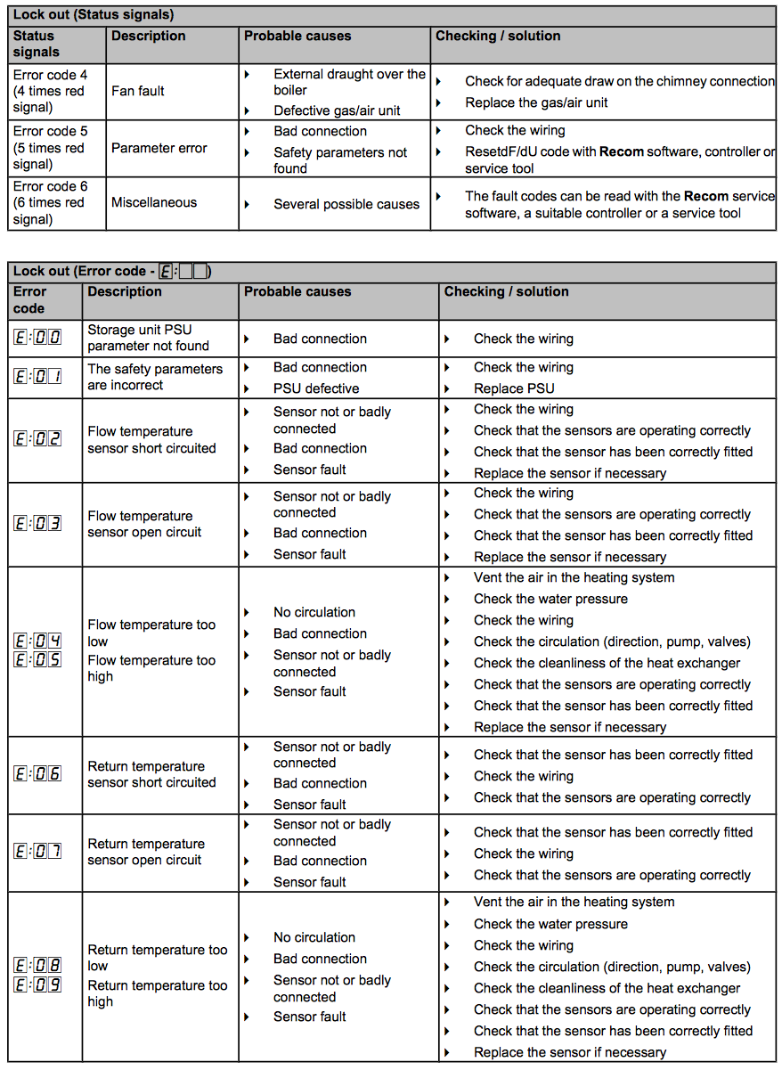
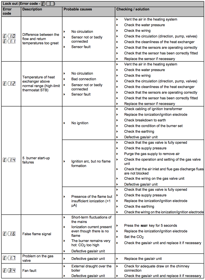
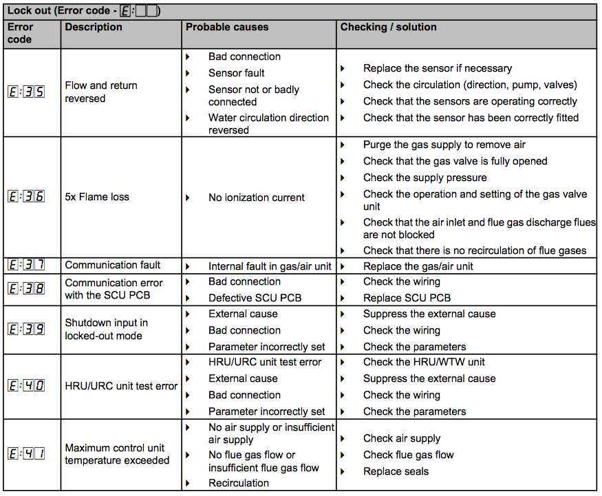
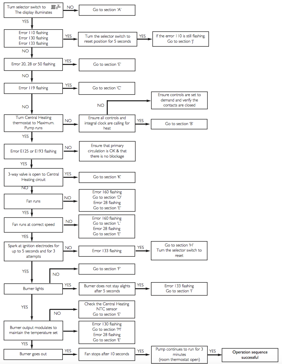
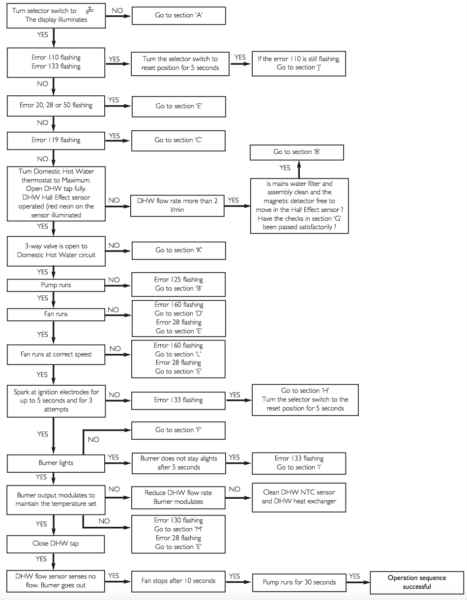
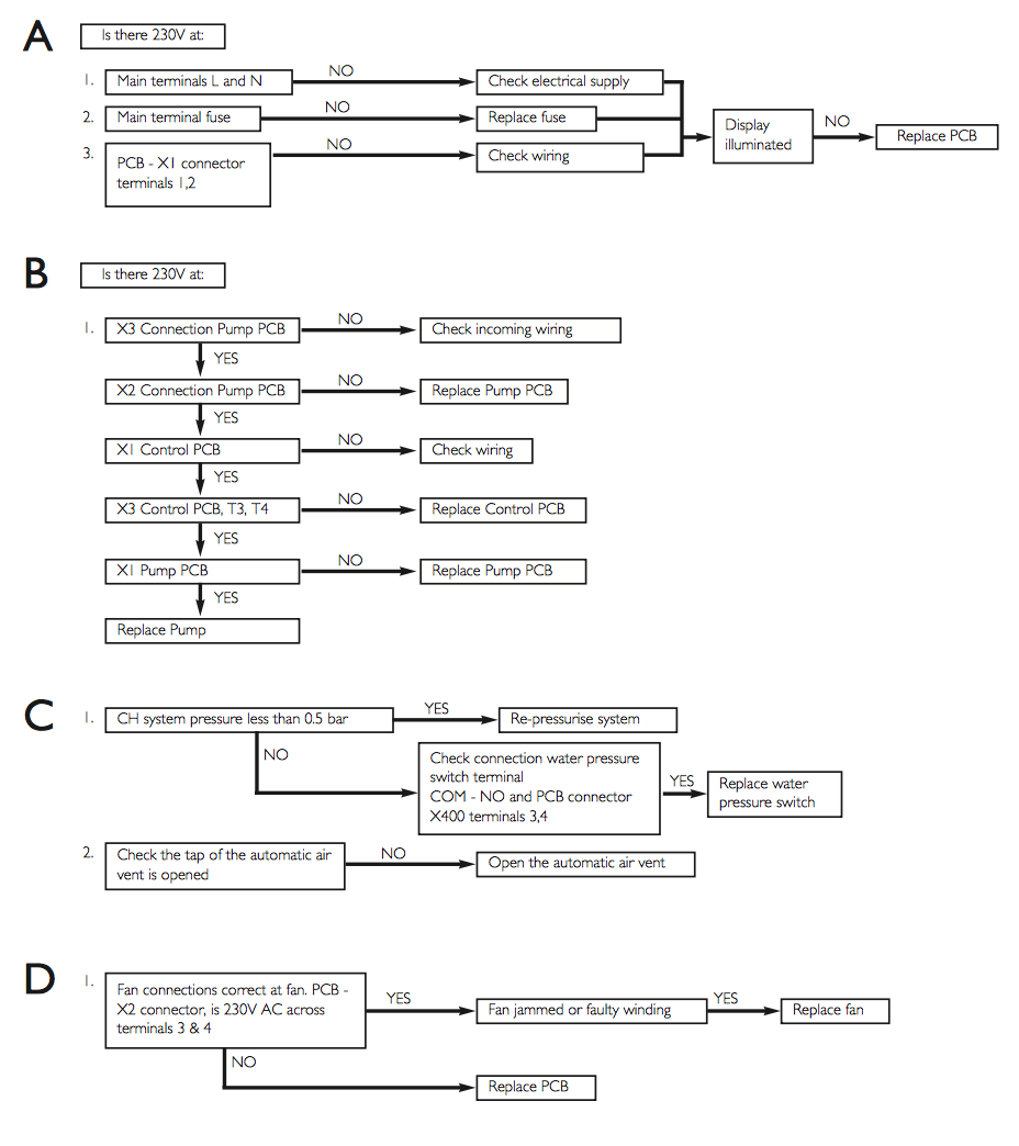
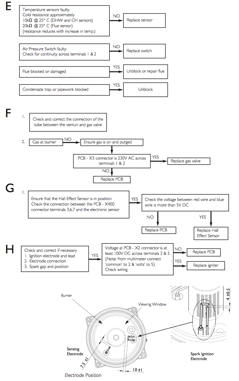
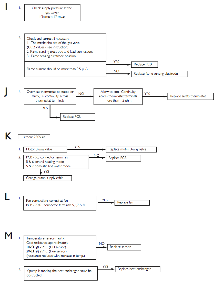
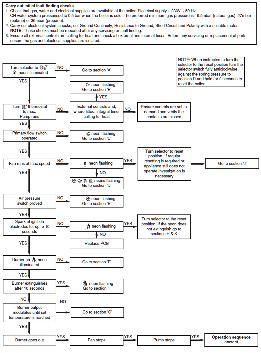
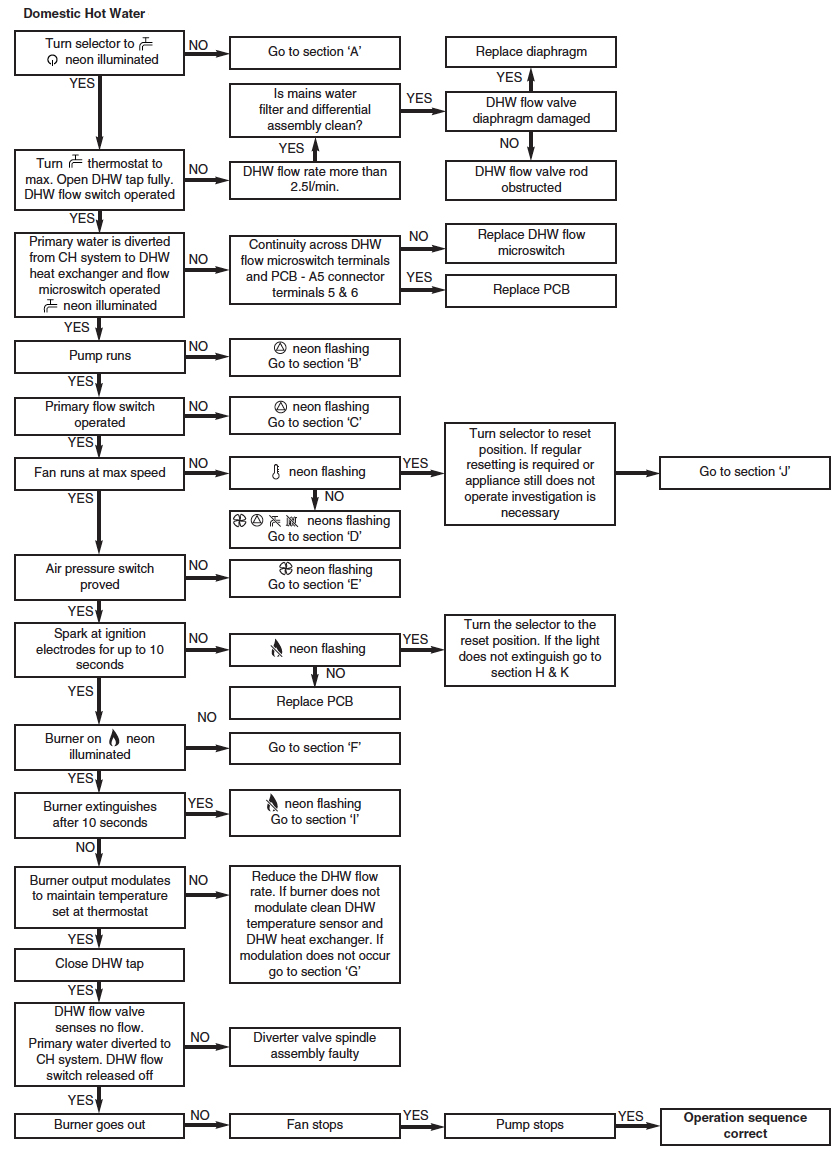
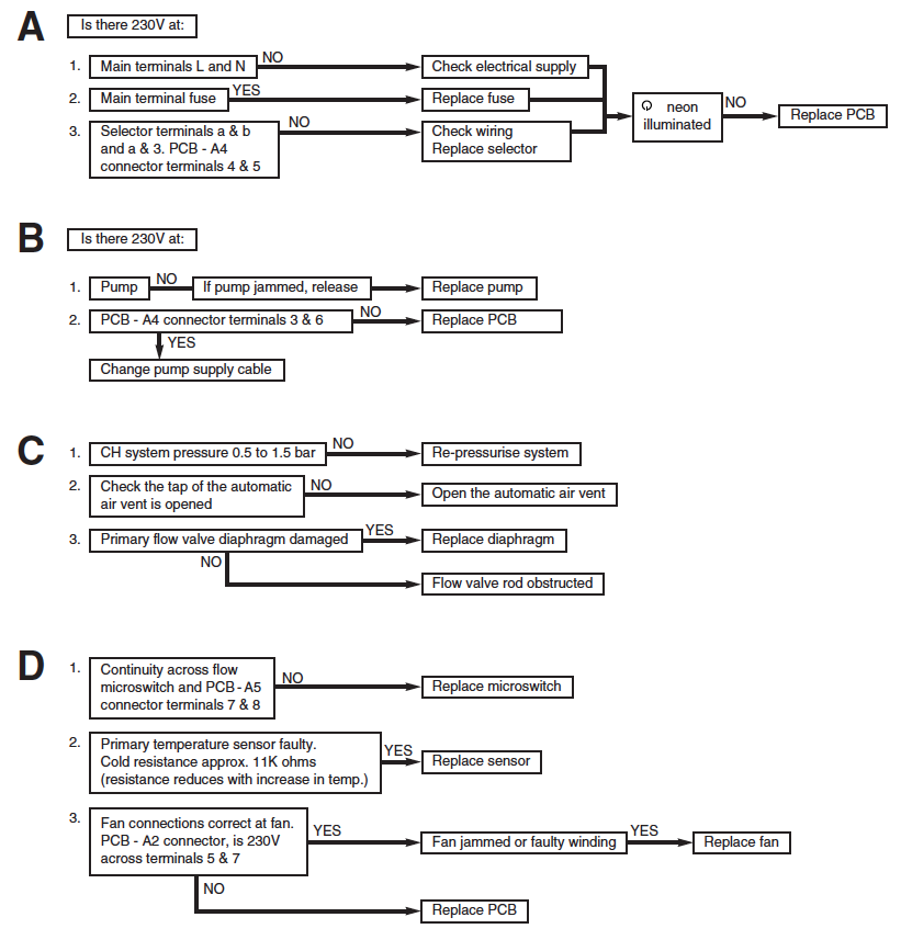
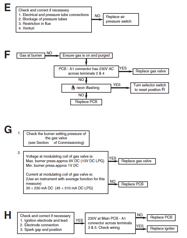
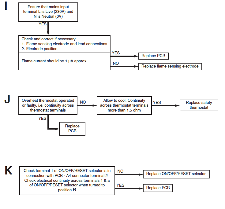
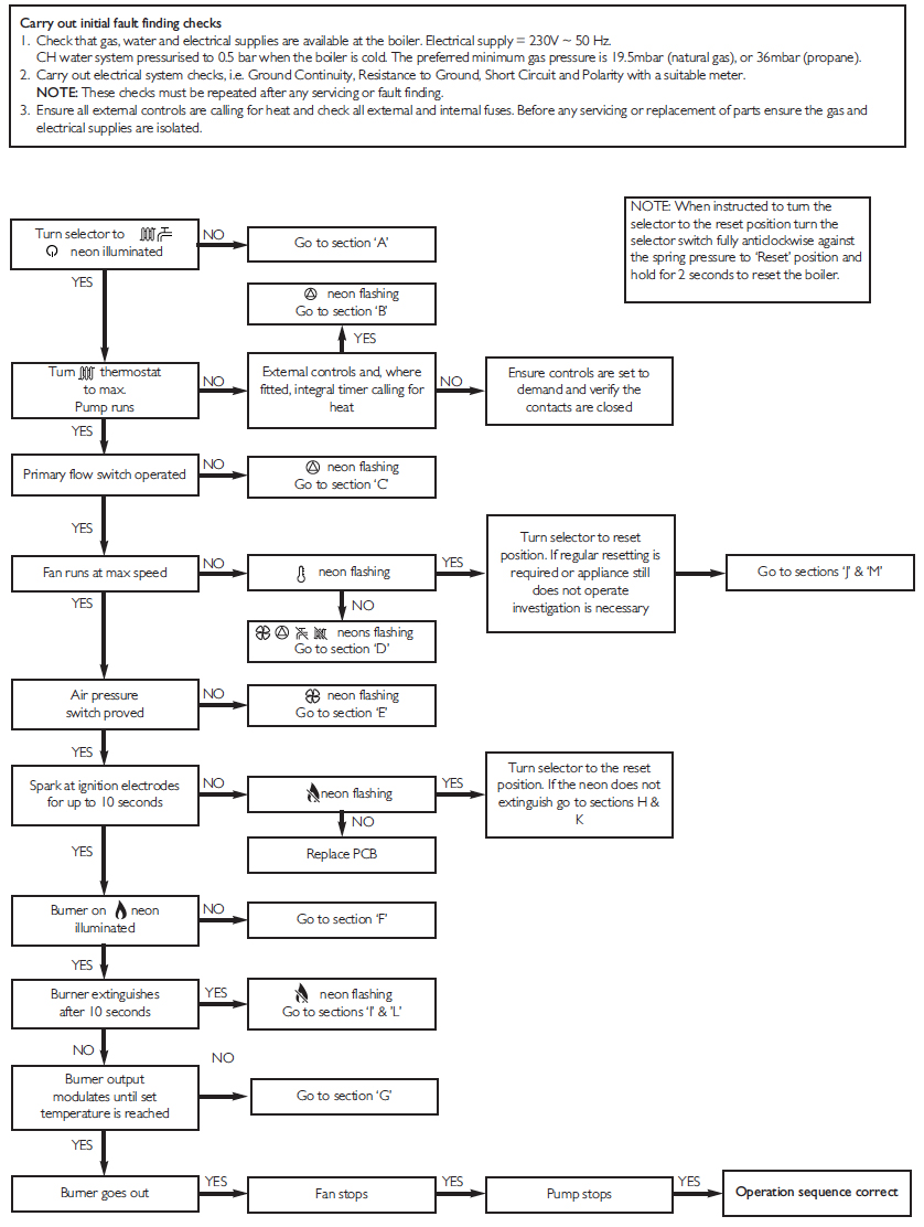
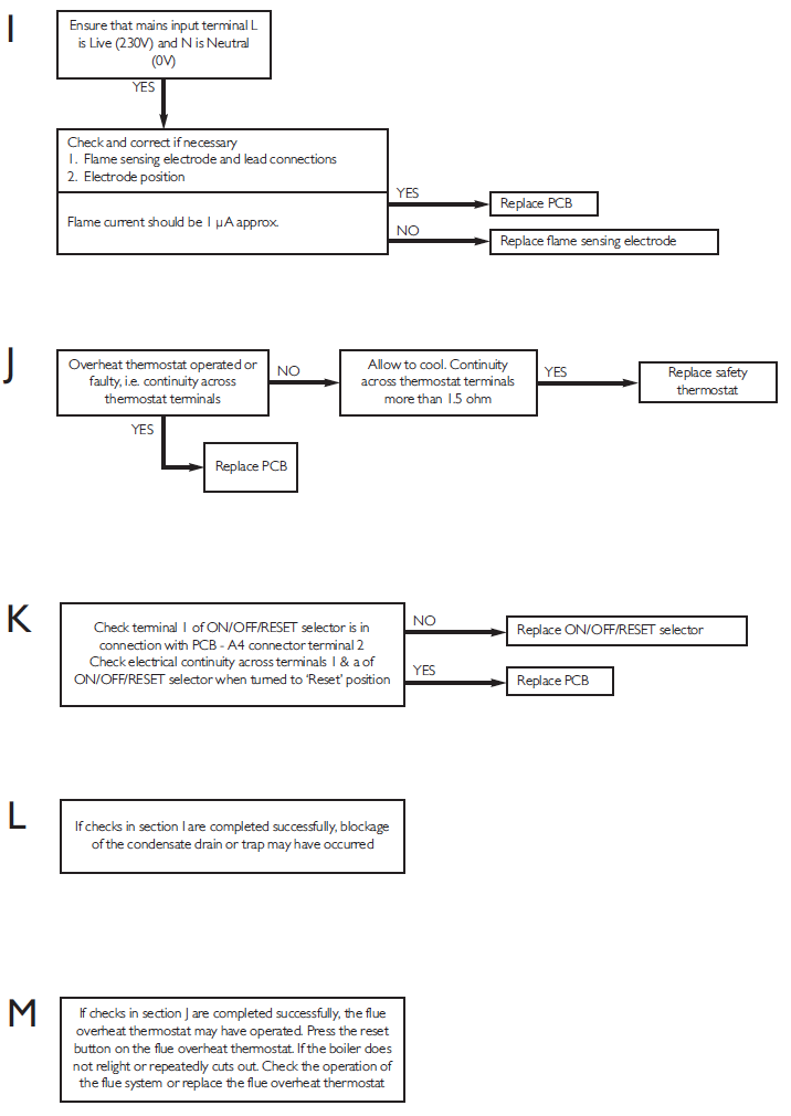
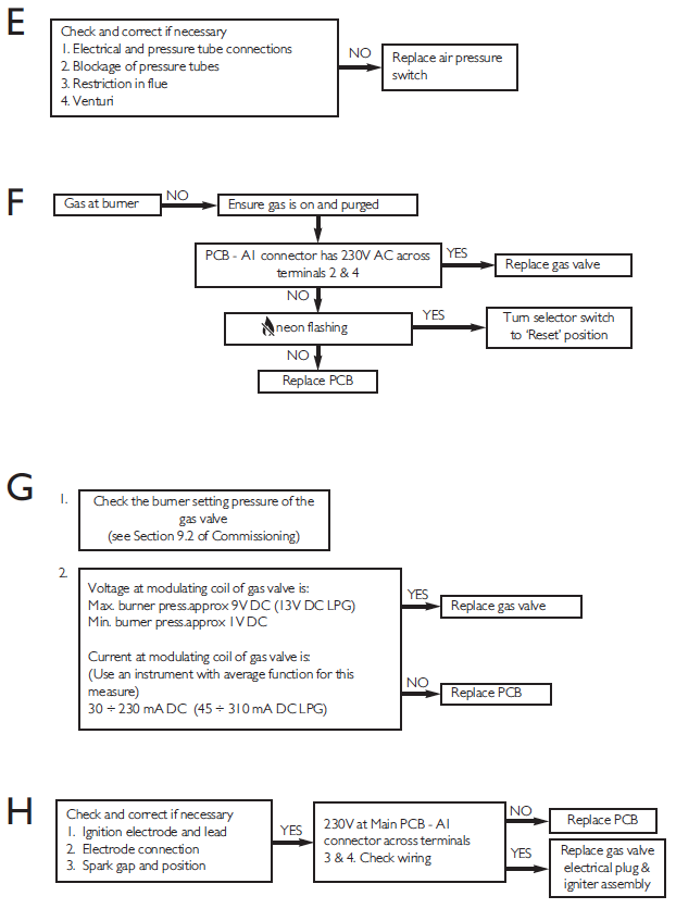
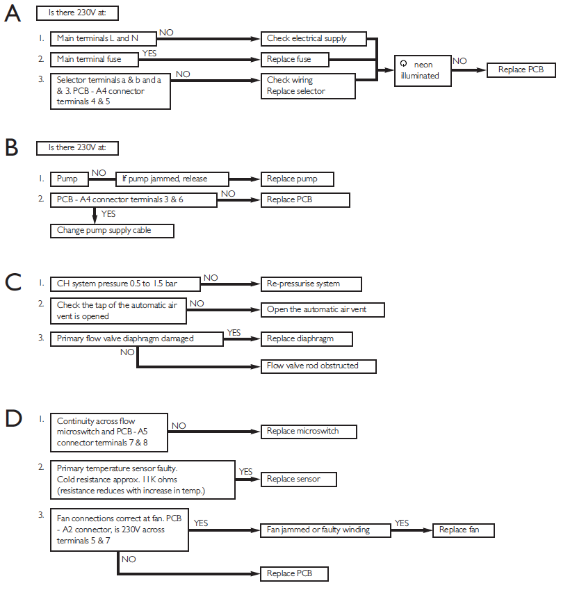
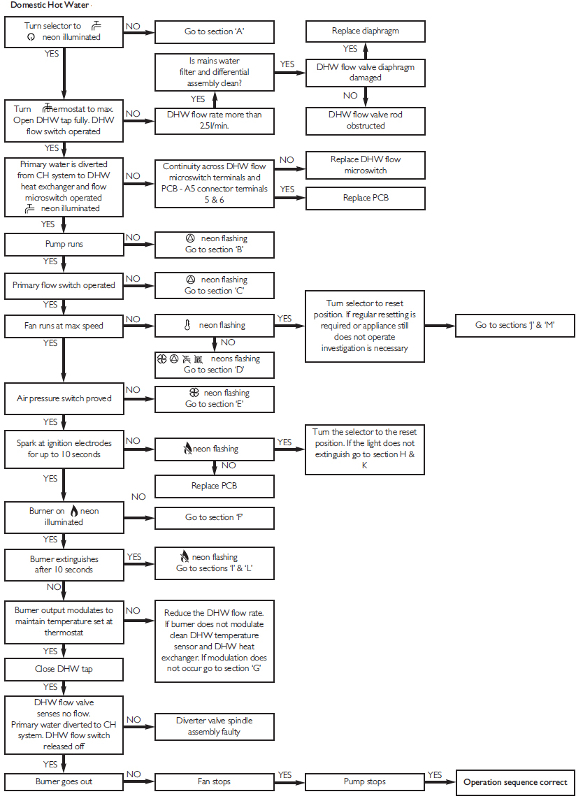
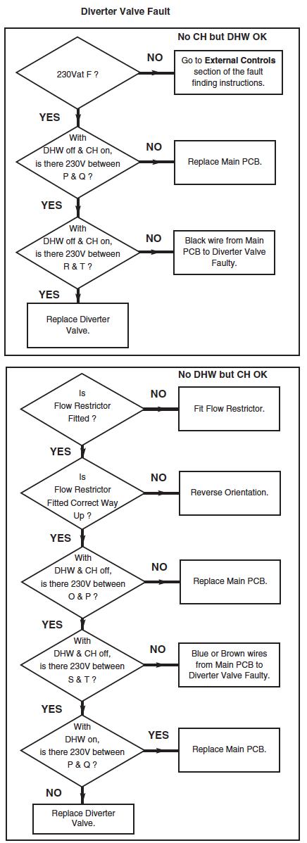
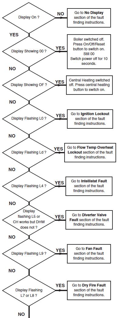
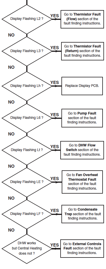
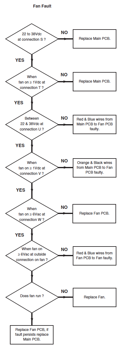
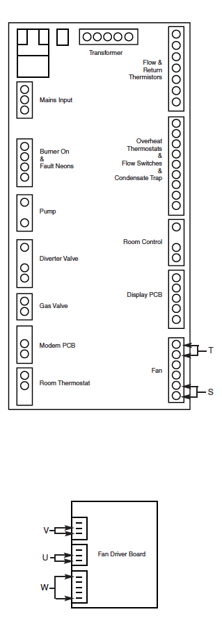
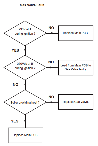
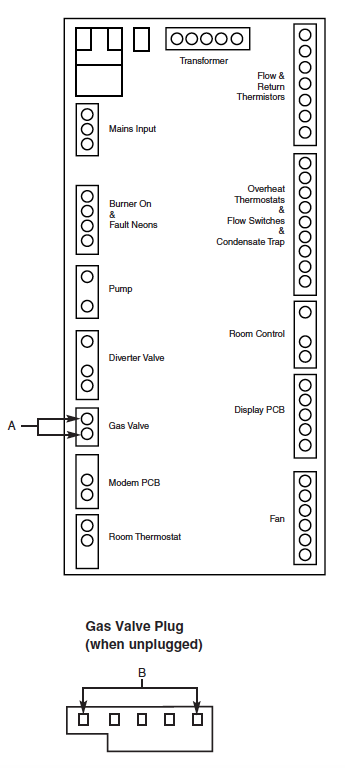
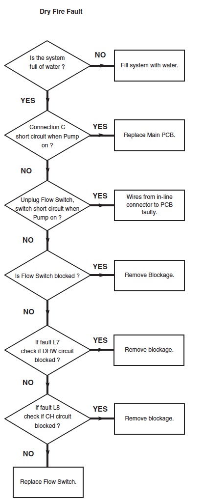
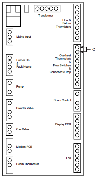
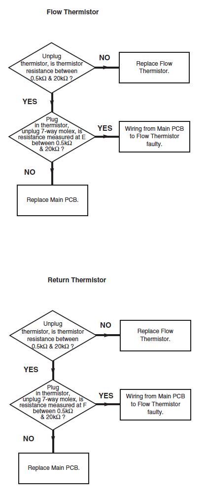
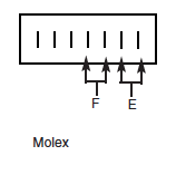
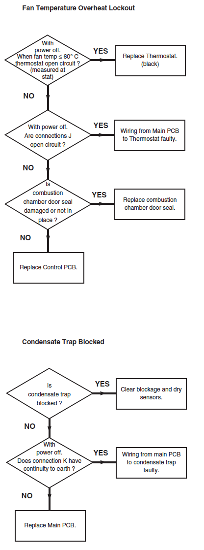
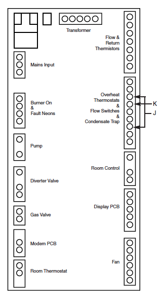
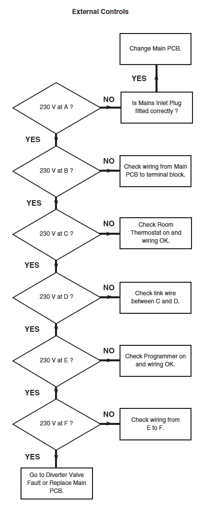
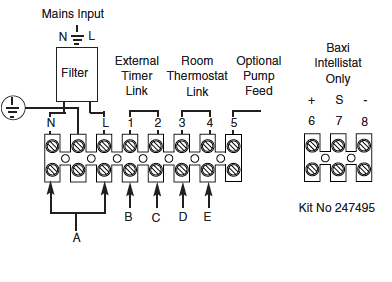
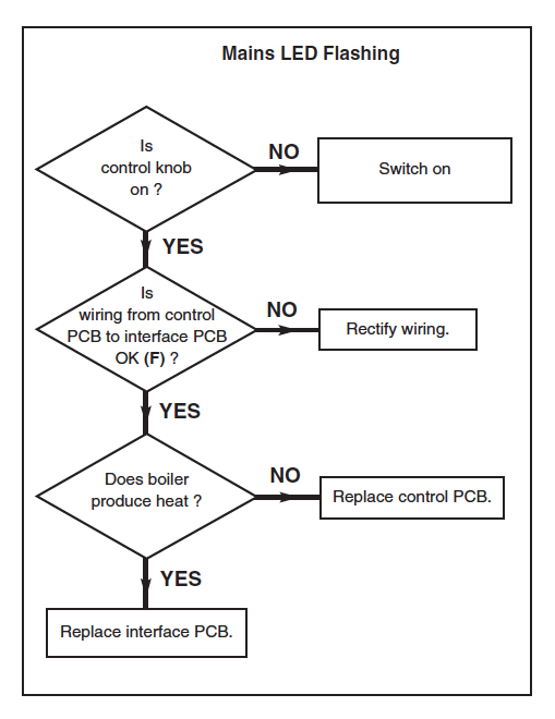
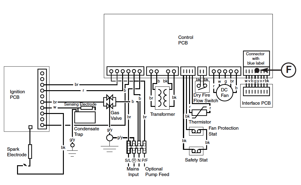
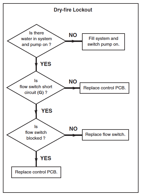
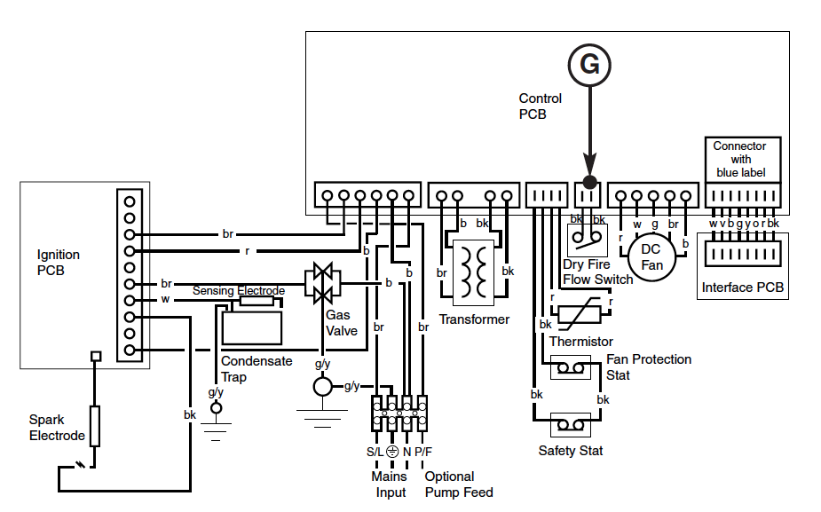
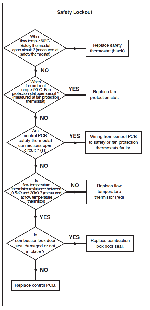
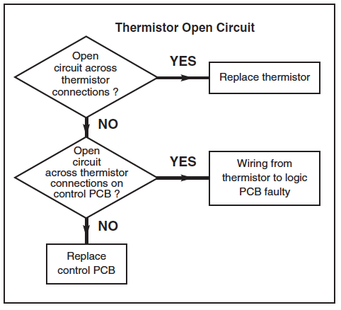
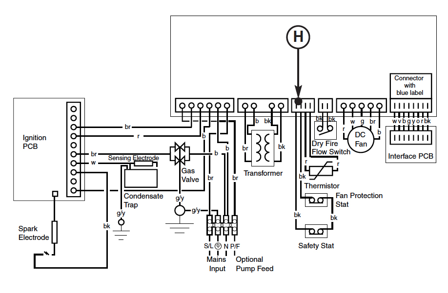
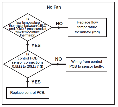
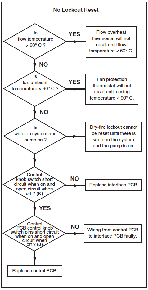
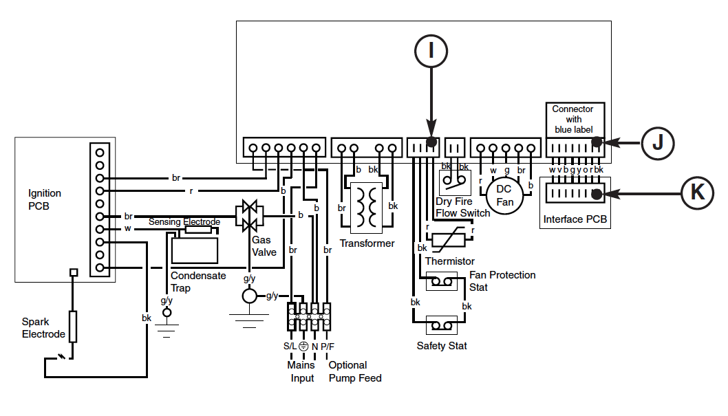
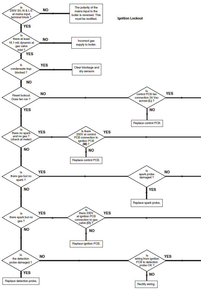
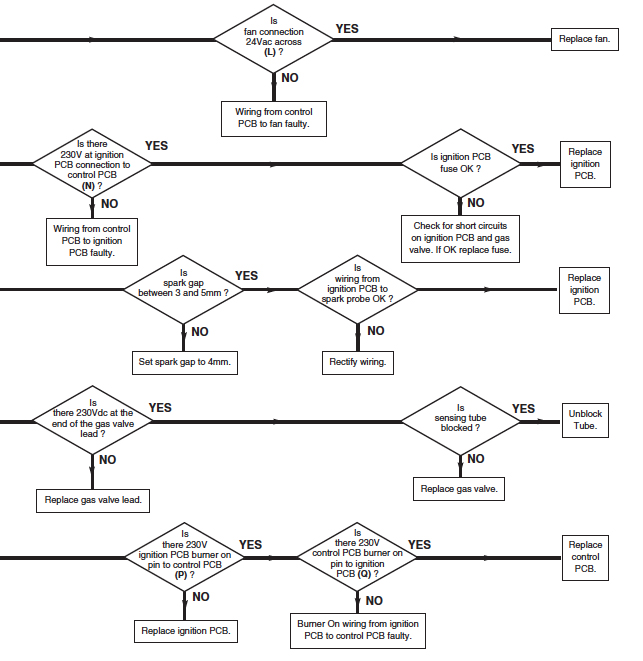
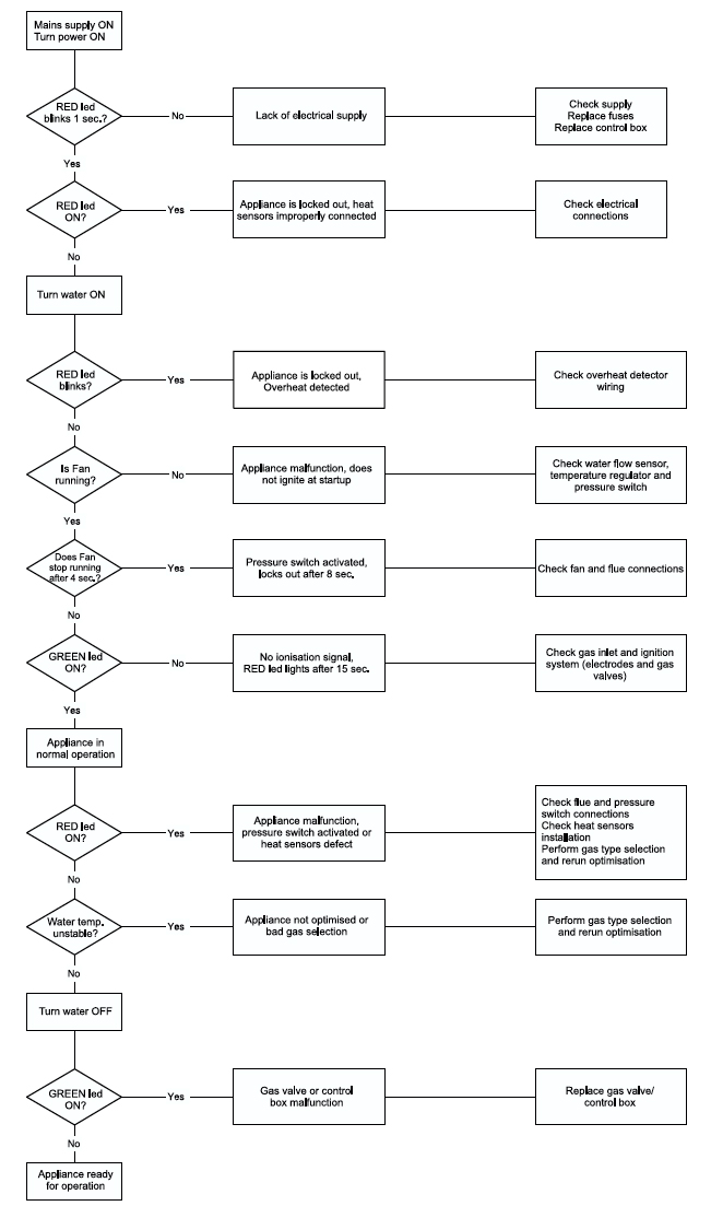
Baxi EcoBlue and Easyflo Fault Finding
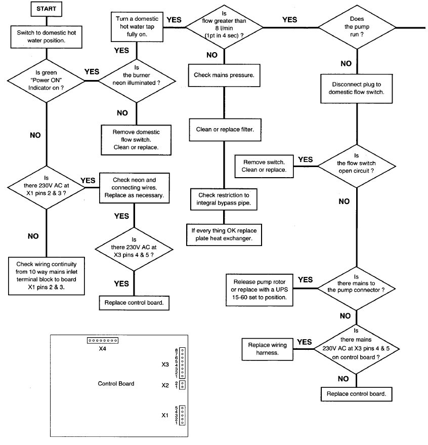
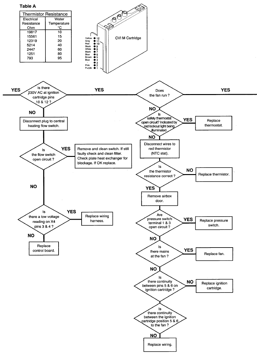
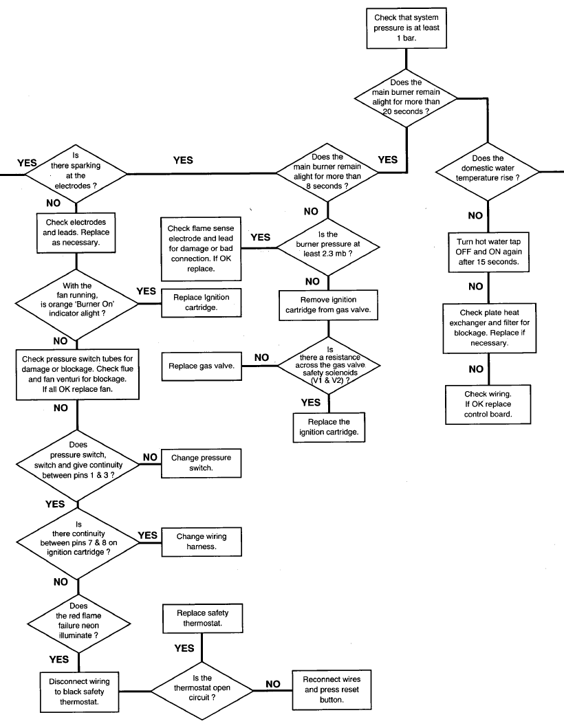
Follow the troubleshooting chart below to trace your Baxi EcoBlue or Easyflo issue and identify your boiler’s diagnosis. You will then be able to find the a suitable replacement part and fix your boiler.

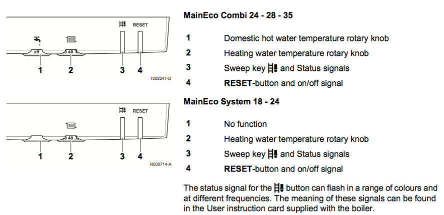
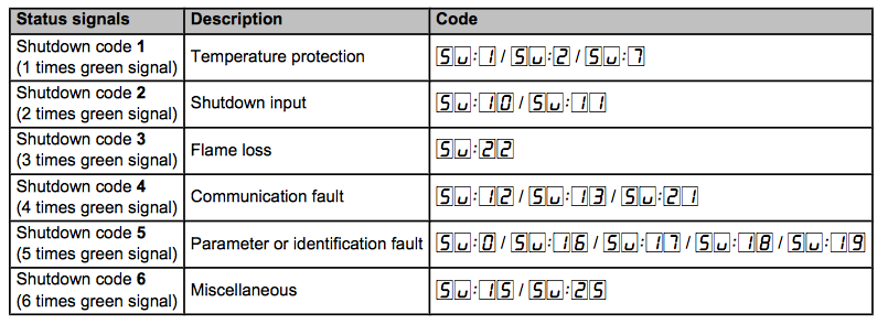
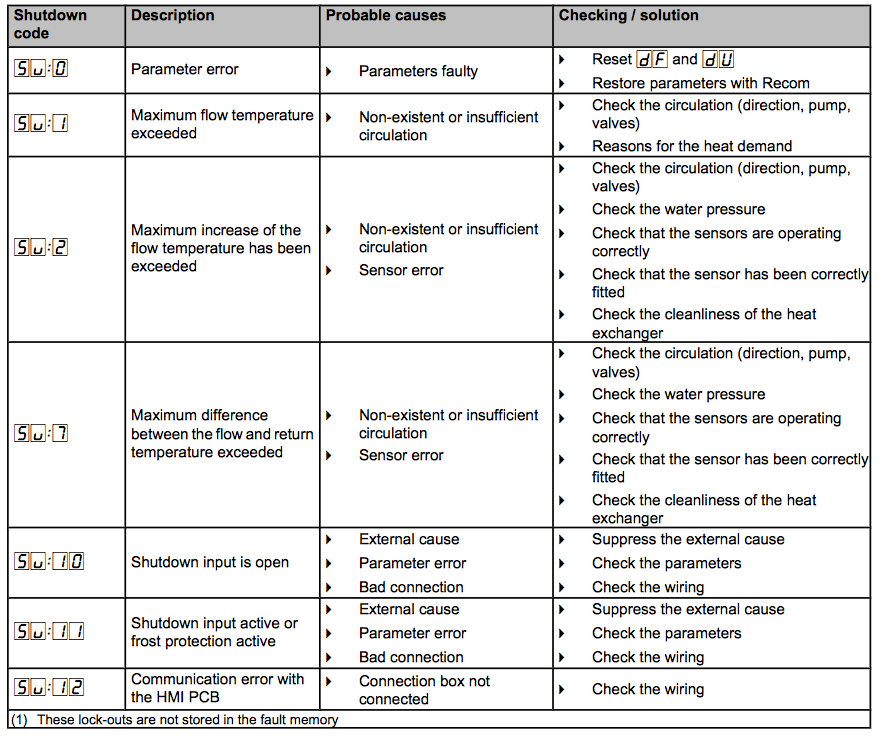
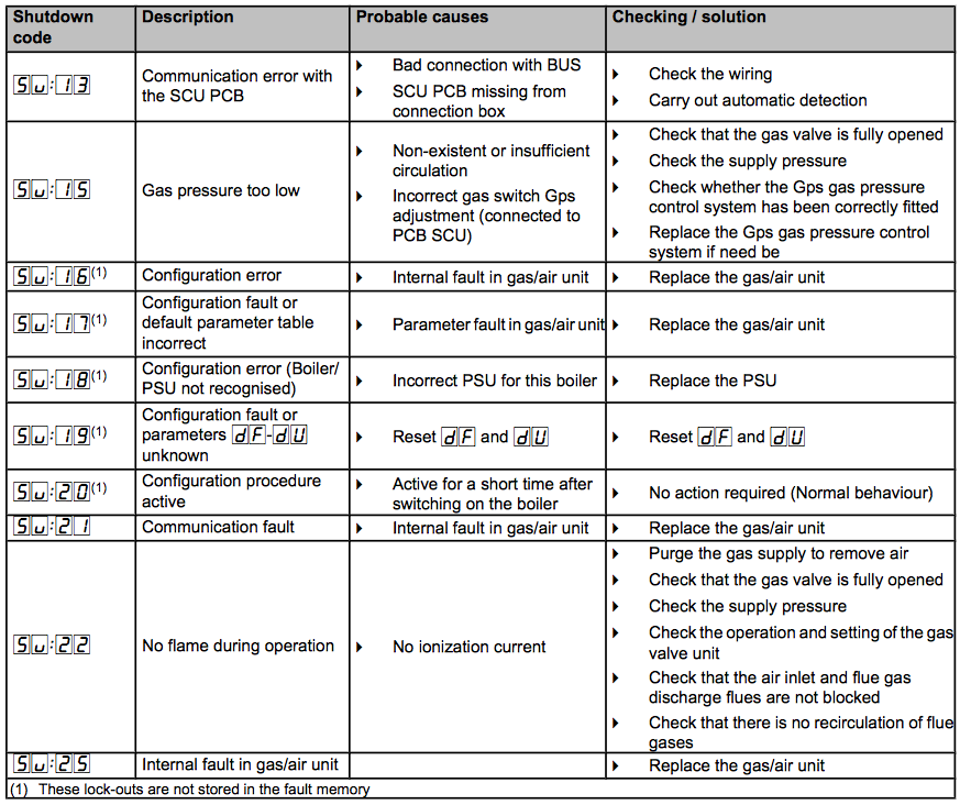
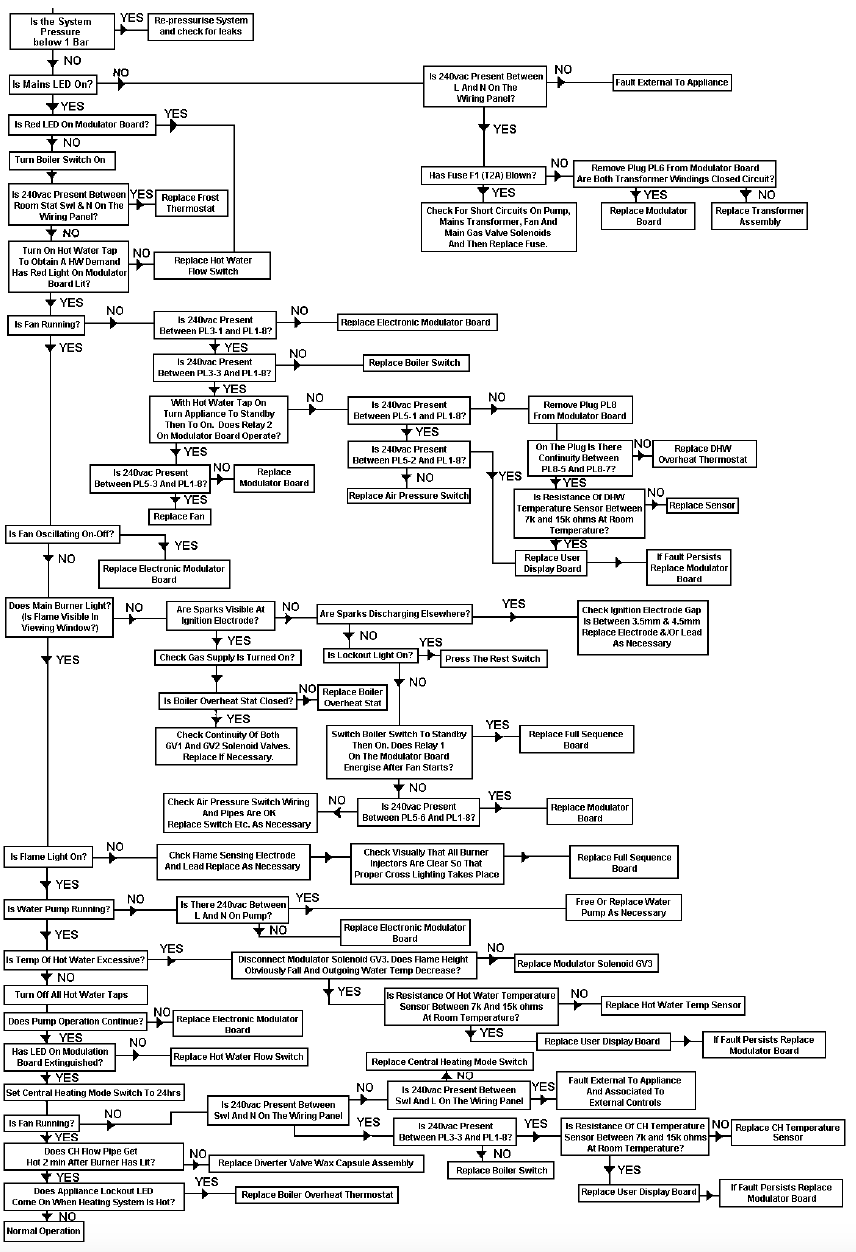
Baxi MainEco Combi and System Boilers Troubleshooting
Check the Baxi MainEco Combi and MainEco System trouble shooting guide below to help you identify your problem and interrogate the replacement part you need.
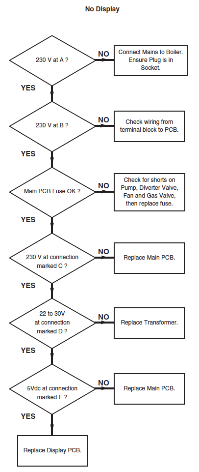
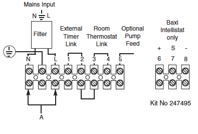
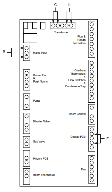
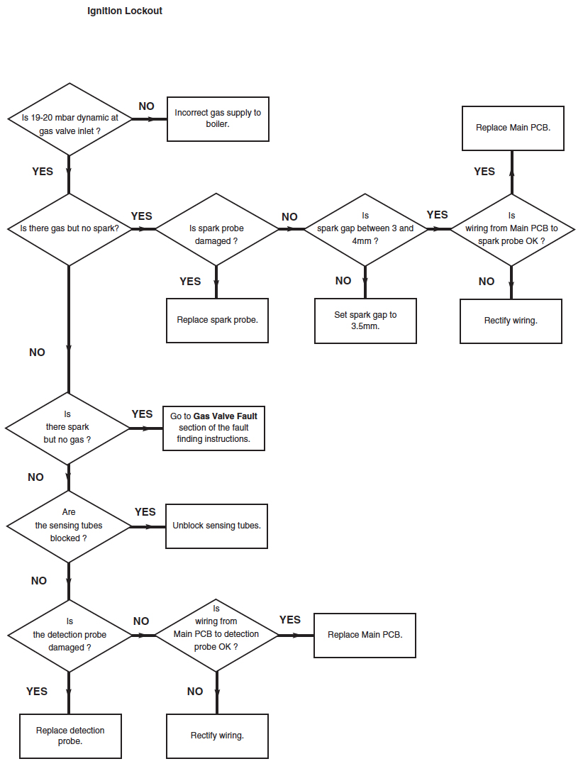
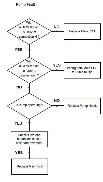
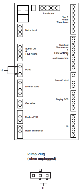
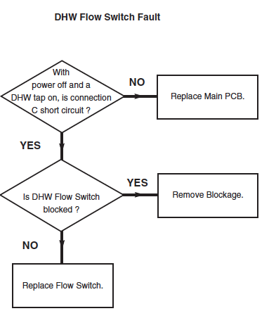
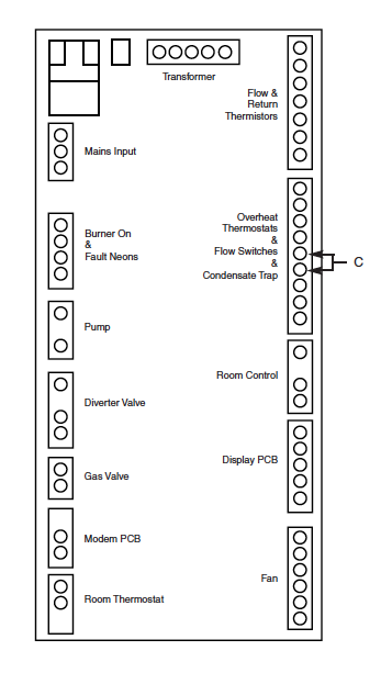
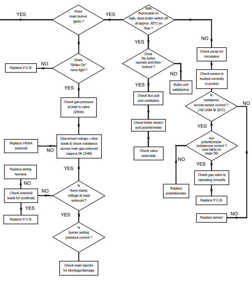
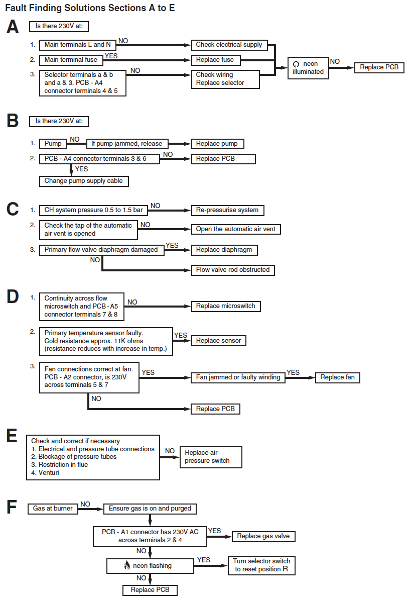
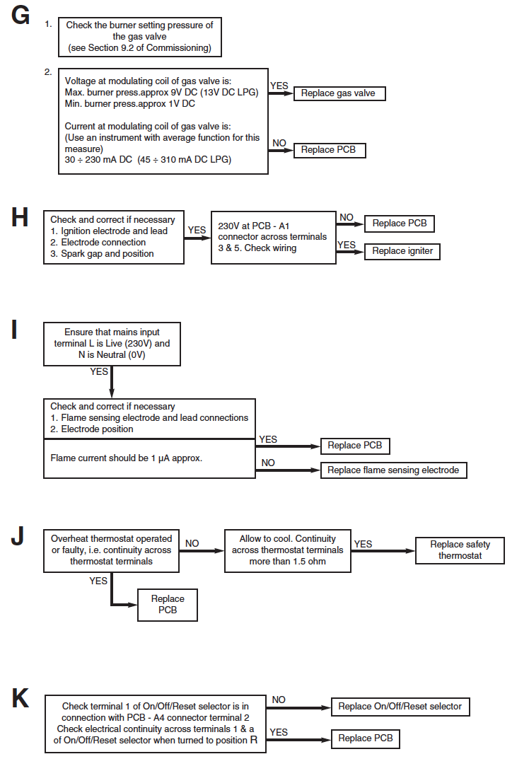
Baxi Platinum Combi Fault Finding
Use the fault finding troubleshooting manual to solve your Baxi Platinum Combi Boiler issue. If necessary you can determine the replacement part required to get your boiler working again.
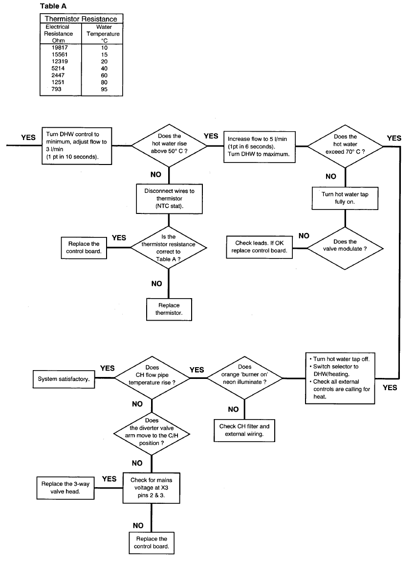
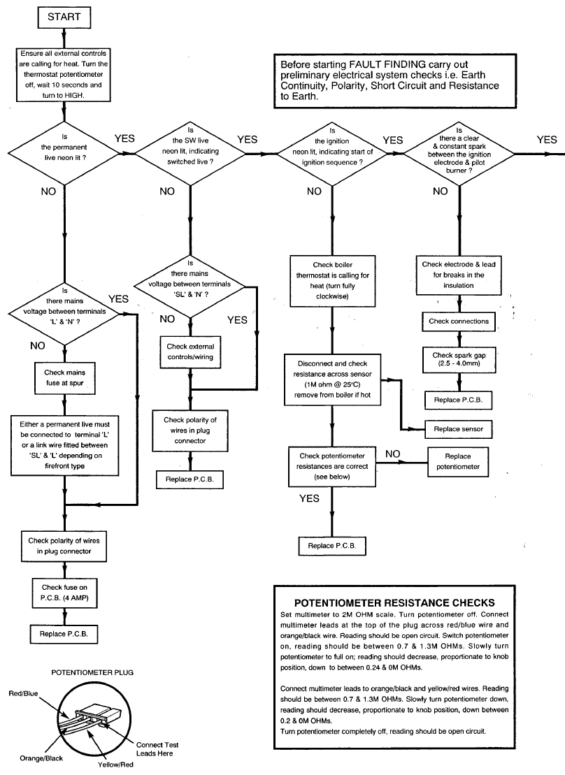
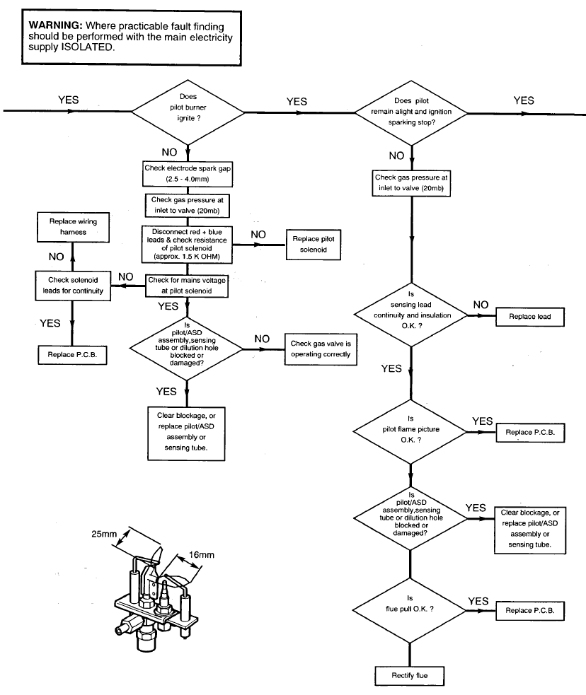
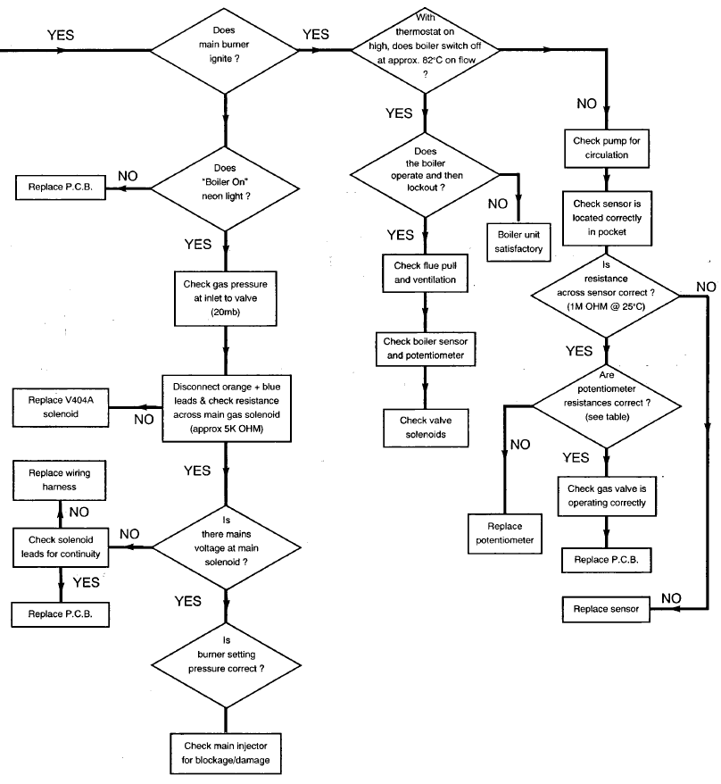
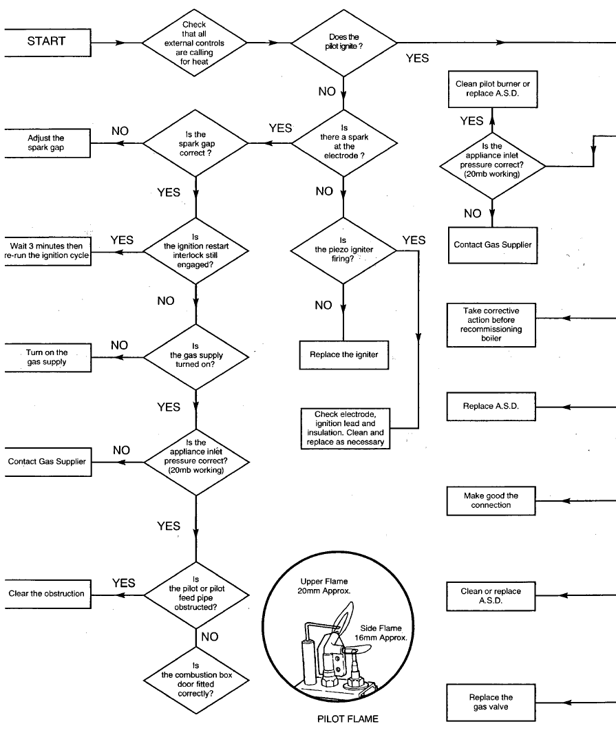
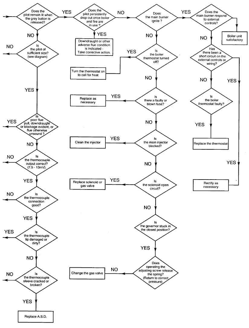
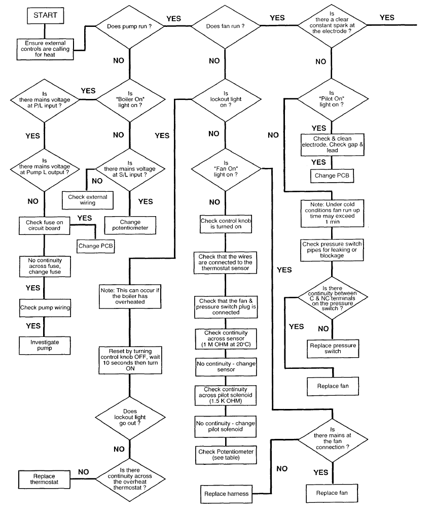
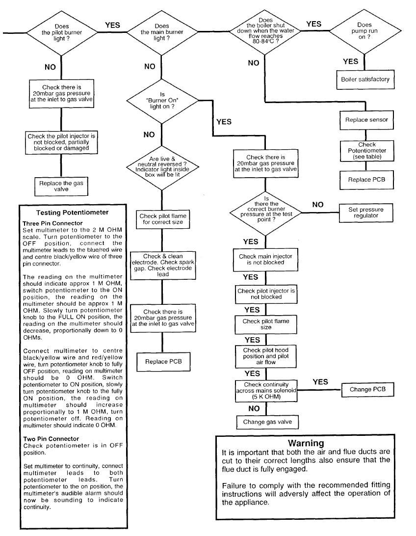
Baxi Combi 80E / 100E Troubleshooting
If your Baxi Combi 80E/100E has a fault, use this simple troubleshooting chart to identify and correct.
Baxi 105HE Fault Finding Guide
The Baxi 105HE troubleshooting charts can be used to interrogate your boiler issue and identify which boiler parts requires replacement.
Baxi Combi 130HE Fault Finding
Use the below suite of fault finding tables and charts to fix your Baxi Combi 130HE Boiler fault. Interrogate the issue to select the appropriate replacement part.
Baxi 100 Troubleshooting
Please use the troubleshooting charts to identify your Baxi 100 Combi Boiler issue and replace parts if necessary.
Baxi Bahama Troubleshooting Manual
Troubleshooting charts to aid you in finding out your Baxi Bahama issue. You can diagnose the issue and find your replacement parts.
Baxi Bermuda Troubleshooting Guide
Find out the issue or replacement part required to fix your Baxi Bermuda fault.
Baxi Bermuda Inset 2 Fault Finding Guide
Check our fault finding guide to troubleshoot your Baxi Bermuda Inset 2 Boiler fault.
Baxi Brazilia Fault Finding Chart
Diagnose your Baxi Brazilia fault with the aid of the helpful fault finding chart.

Combi 80 Troubleshooting Chart
Check out the Baxi Combi 80 Fault finding chart to diagnose your fault and if necessary identify the replacement part.
Baxi Genesis Fault Finding Guide
Inspect the fault finding chart below to identify your Baxi Genesis problem. If required you can identify the replacement part required to fix your unit.
Baxi System 35/60 & 60/100 Fault Finding Guide
Use the fault finding tables below to help find your Baxi System 35/60 or 60/100 problem, should you need a specific replacement part you can locate that here also.

Multipoint FF Troubleshooting Tables
Check out the fault finding diagram below to locate your Baxi Multipoint FF issue. If required you can locate the replacement part required to get your boiler operational once more.
Multipoint BF Fault Finding Table
Use the Baxi Multipoint BF Fault Finding table below to determine the problem with your boiler and if necessary identify the replacement parts you need.
| Problem | Cause | Solution |
|---|---|---|
| Incorrect water temperature | Incorrect gas rate. | Check the gas supply to appliance gas isolation valve. |
| Open the gas isolation valve. | ||
| Check the burner pressure. | ||
| Check the inlet pressure. | ||
| Water section sticking or faulty. | Clean or replace. | |
| Incorrect water flow rate. | Incoming supply valve closed. | Open supply valve. |
| Low water pressure. | Check the water pressure is above 0.2 bar. | |
| Water section sticking or faulty. | Clean or replace. | |
| Noise. | Scale in heat exchanger. | Descale and service. |
| High gas rate. | Check the burner pressure. | |
| Low water flow rate. | Check the water flow rate. | |
| Pilot flame will nor light or stay lit. | No gas supply. | Connect gas supply. |
| Gas isolation valve closed. | Open gas isolation valve. | |
| Air in gas line. | Purge the line. | |
| Pilot injector blocked. | Clean/replace the injector. | |
| No spark. | Clean or replace the electrode, Piezo unit or cable. | |
| Main burner will not light. | Gas pressure low. | Check the inlet and burner pressure. |
| Gas isolation valve partially closed. | Open the gas isolation valve. | |
| Low water rate | Check the water rate. | |
| Water section diaphragm faulty. | Replace the diaphragm. | |
| Gas valve faulty. | Replace the gas valve. | |
| Explosive ignition. | Reduced pilot flame. | Clean or replace the pilot injector assembly. |
| Faulty show ignition valve. | Replace the show ignition valve. |
Medway Super Troubleshooting
If you have a breakdown with your Baxi Medway Super system use the troubleshooting table below to diagnose your problem so you can then order the correct replacement parts.
| Symptom | Possible Cause | Solution |
|---|---|---|
| SMELL OF COMBUSTION PRODUCTS | 1. Faulty case or terminal seal | 1. Check that the outer case seal - Part No 10/1 7501 and terminal seal - Part No 31/12299 are in good condition, replace if necessary. Ensure the outer case is correctly positioned. |
| 2. Failure to follow instructions with regards to openable windows and doors | 2. Re-site the appliance. | |
| UNEXPLAINED SHUT-DOWN OF THE APPLIANCE | Temperature selector set too high for the time of year. | Select a lower temperature. |
| Excessive resistance of push rod. | Exchange push rod and seals. Lubricate with Dow Corning III silicone grease and ensure free movement. | |
| LOW WATER TEMPERATURE | 1. Temperature selector set to '-' . | 1. Turn selector to '+'. |
| 2. Gas pressure too low. | 2. Check and clean gas filter, also check gas inlet pressure. | |
| 3. Faulty diaphragm. Will also cause a high water rate. | 3. Replace the diaphragm assembly - Part No 10/17534. | |
| 4. Automatic gas valve push rod sticking. May also cause a high water rate. | 4. Dismantle dean and regrease using Dow Corning 111 silicone grease. Handle the push rod with care, do not bend. | |
| 5. Slow ignition screw incorrectly set. Will also cause a high water rate. | 5. See Fig, 16 for the position of the screw. Turning the screw clockwise delays the ignition, anti-clockwise advances the ignition. The screw should be set 2 full turns out (anti clockwise) from the fully in position. When correct the burner ignition should be smooth and quiet when a hot water outlet is opened. | |
| NOISY HEATER | 1. Heat exchanger scaled. Ultimately this will cause the heat exchanger fins to discolour and buckle. | 1. Descale or replace - Part No 10/1 7558 |
| 2. Noisy ignition could be caused by incorrect setting of the show ignition screw. | 2. See Fig, 16 for the position of the screw. Turning the screw clockwise delays the ignition, anti-clockwise advances the ignition. The screw should be set 2 full turns out (anti clockwise) from the fully in position. When correct the burner ignition should be smooth and quiet when a hot water outlet is opened. | |
| 3. Reduced pilot rate caused dy dirt. | 3. Clear injector by blowing through or replace with pilot injector Part No 19/12690. Also clean the lint filter located at the base of pilot tube. | |
| 4. Burner aeration ports and main flame ports blocked. | 4. Carefully clean the burners with a vacuum cleaner. | |
| PILOT LIT BUT MAIN BURNER WILL NOT LIGHT ON WATER FLOW | 1. Gas inlet pressure low. | 1. Call in your local British Gas Region. |
| 2. Low waterflow caused by blocked water filter. | 2. Clean the debris from the filter. | |
| 3.Faulty diaphragm. Will also cause as high water rate. | 3. Replace the diaphragm assembly - Part No 10117534. | |
| 4. Automatic gas valve push rod jammed. May also cause a high water rate. | 4. Dismantle dean and regrease using Dow Corning 111 silicone grease. Handle the push rod with care, do not bend. | |
| 5. Slow ignition screw incorrectly set. Will also cause a high water rate. | 5. See Fig, 16 for the position of the screw. Turning the screw clockwise delays the ignition, anti-clockwise advances the ignition. The screw should be set 2 full turns out (anti clockwise) from the fully in position. When correct the burner ignition should be smooth and quiet when a hot water outlet is opened. | |
| NO OR LOW WATER FLOW RATE | 1. Blocked water filter. | 1. Clean the debris from the filter. |
| 2. Heat exchanger blocked with lime. | 2. Descade or replace - Part No 10/17758 | |
| 3. Loss of service water main pressure. | 3. Contact your Local Water Authority. | |
| 4. Low water pressure. | 4. Check that the low pressure inlet has been used and that the low pressure throttle kit ( P/N 31/17756) has been fitted. | |
| HIGH WATER FLOW RATE | See LOW WATER TEMPERATURE | |
| HIGH WATER TEMPERATURE | 1. Automatic gas valve push rod sticking. Water rate will be normal. | 1. Dismantle dean and regrease using Dow Corning 111 silicone grease. Handle the push rod with care, do not bend. |
| PILOT WILL NOT LIGHT | 1. Gas not turned on. | 1. Turn on the gas at the gas service cock and/or the main gas line. |
| 2. Air in gas line. | 2. Purge the air line by depressing and holding the centre ON button, this may take 2-3 minutes. | |
| 3. Incorrect pilot lighting procedure. | 3. Follow the lighting instructions located on the bottom cover or refer to the "Instructions for Use". | |
| 4. Electrode lead not connected to the rear of the spark igniter. | 4. Re-connect the electrode lead. | |
| 5. Incorrect spark gap. | 5. The gap between the electrode tip and the pilot hood should be 3-4 mm. | |
| 6. Current tracking to earth. | 6. Check the electode lead is routed clear of all metal parts. | |
| 7. Pilot injector blocked. | 7. Clear injector by blowing through or replace with pilot injector Part No 19/12690. Also clean the lint filter located at the base of pilot tube. | |
| 8. Faulty components. | 8. Replace any faulty components found. Piezo Unit- Part No 10/11935. Electrode Assembly Part No 10/1 7493. | |
| 9. No gas to the appliance | 9. Call in your local British Gas Region. | |
| PILOT LIGHTS BUT WILL NOT REMAIN ALIGHT | 1. Thermocouple connections loose. | 1. Tighten the connections. |
| 2. Pilot flame 'soft' or too small to heat the thermocouple tip. | 2. Pilot injector partially blocked, clear by bowling through or replace. Check the gas inlet pressure is correct - 20 mbar. Also clean the lint filter located at the base of the pilot tube. | |
| 3. Thermocouple worn out or damaged. | 3. Replace the thermocouple - Part No 10/17461. | |
| 4. Faulty magnet unit in the flame safety device. | 4. Replace flame safety device - Part No 10/1 3477 | |
| 5. Energy cut-off device connections loose. | 5. Tighten connections. | |
| 6. Energy cut-off device may be faulty. | 6. Check for continuity and replace if necessary - Part No 10/17792. |
Baxi Solo 2 Fault Finding Tables
Check out the Baxi Solo 2 Troubleshooting tables to help you correct the issue with your boiler. Order replacement parts as identified by the fault finding guide.
| Problem | Symptom | Possible Causes |
|---|---|---|
| Gas Leak | Gas leak at joint on valve body on soap solution test. | Loose screws at joints or fittings - detective "O" ring damaged valve casting at joint - defective burner feed pipe. |
| Burner | Pilot on but burner will not ignite. | External controls or boiler thermostat not calling for heat - blown fuse - defective power supply or external controls - soleniod open circuit (test for continuity at solenoid terminals) - injector blocked - inadequate gas supply - faulty gas valve. |
| Pilot established and main burner will ignite but system liable to nuisance shut - down. | Dirty or loose thermocouple connections - defective thermocouple - defective flame safety magnet - incorrect or faulty wiring - overheat cut-off device defective - adverse wind conditions - incorrectly filled terminal - partially blocked pilot injector. | |
| Main burner will not shut down in response to external controls. | Short circuit in external controls or wiring - defective solenoid - faulty main thermostat (Check continuity between S/L on terminal strip and 1 (L) on plug on gas valve.) | |
| Main burner pressure incorrect. | Throttle screw requires adjustment - (after adjustment recheck pressure). | |
| Overheat Thermostat | Overheat cut-off device operates repeatedly. | System temperature higher than design temperature - main thermostat faulty - overheat thermostat faulty - central heating pump not functioning correctly - pump overrun timer faulty- no by- pass-by-pass closed - installation fault - no permanent live - pump not wired to boiler - incorrect use i.e. turning off at isolation switch. |
| Overheat thermostat reset but boiler cannot be reignited. | Thermocouple damaged - connections between thermocouple, overheat thermostat and gas valve faulty or poor - overhear thermostat faulty. | |
| Pilot | Pilot will not light. | Main gas tap off - ignition restart interlock is still engaged - gas control knob not fully depressed - pilot feed not purged of air - pilot feed blocked - pilot injector blocked - electrode lead or ignitor faulty - overheat cut-off device has operated - if on gravity, overheat thermostat wires may not be piggybacked. |
| Pilot established when gas control knob released but pilot flame does not fully envelop the thermocouple. | Incorrect or faulty pilot injector fitted - pilot injector partially blocked. | |
| Pilot lights but goes out when gas control knob is released. | Gas control knob released too soon - dirty or loose connections - defective thermocouple or flame safety magnet - overheat cut-off device activated - partially blocked pilot injector. | |
| Main burner will ignite but pilot flame is immediately extinguished. | Incorrect pilot injector - gas supply too small or restricted - adverse wind conditions - incorrectly filted terminal - partially blocked pilot injector. |
Baxi Solo 3 Troubleshooting Charts
Baxi Solo 3 troubleshooting charts are useful for diagnosing the problem with your boiler and identifying a replacement part to get your boiler operation again.
Thames Troubleshooting Manual
Diagnose your Baxi Thames Boiler with the useful fault finding tables below. If you need replacement parts use the fault finding table to determine the troubled component.
| Symptom | Possible Cause | Solution |
|---|---|---|
| UNEXPLAINERD SHUT-DOWN OF THE APPLIANCE | Failure of the appliance thermostat. | Repair or replace. |
| Excessive resistance of push rod. | Exchange push rod and seals, Lubricate with Dow Coming III silicone grease and ensure free movement. | |
| PILOT LIT BUT MAIN BURNER WILL NOT LIGHT ON WATER FLOW | 1.Gas inlet pressure low. | 1.Call in your local British Gas Region |
| 2.Low water flow caused by blocked water filter. | 2.Clean the debris from the filter. | |
| 3.Faulty diaphragm. Will also cause a high water rate. | 3.Replace the diaphragm Assembly - Part No 10/17534. | |
| 4.Automatic gas valve push rod jammed. May also cause a high water rate. | 4.Dismantle dean and regrease using Dow coming 111 silicone grease. Handle the push rod with care, do not bend. | |
| 5.Slow ignition screw incorrectly set Will also cause a high water rate. | 5.See Fig. 16 for the position of the screw. Turning the screw clockwise delays the ignition, anti-clockwise advances the ignition. The screw should be set 2 full turns out (anti clockwise) from the fully in position. When correct the burner ignition should be smooth and quiet when a hot water outlet is opened. | |
| 6.Thermostat throttle stuck in the open position. Will also cause a high water rate. | 6.Descale, regrease and replace 'O' rings as necessary. | |
| NO OR LOW WATER FLOW RATE | 1.Blocked water filter. | 1.Clean the debris from the filter. |
| 2.Heat exchanger blocked with lime. | 2.Descale or replace - Part No 10/17667. | |
| 3.Loss of service water main pressure. | 3.Contact your Local Water Authority. | |
| HIGH WATER FLOW RATE | See LOW WATER TEMPERATURE | |
| HIGH WATER TEMPERATURE | 1.Automatic gas valve push rod sticking. Water rate will be normal. | 1.Dismantle dean and regrease using Dow Coming 111 silicone grease. Handle the push rod with care, do not bend. |
| 2.Thermostat bellows perforated. | 2.Replace thermostat assemble - Part No 10/13486. | |
| LOW WATER TEMPERATURE | 1.Temperature selector set to '1'. | 1.Turn selector to '5'. |
| 2.Gas pressure too low. | 2.Check and clean gas filter, also check gas inlet pressure. | |
| 3.Faulty diaphragm. Will also cause a high water rate. | 3.Replace the diaphragm assembly - Part No 10/17534. | |
| 4.Automatic gas valve push rod sticking. May also cause a high water rate. | 4.Dismantle clean and regrease using Dow coming 111 silicone grease. Handle the push rod with care, do not bend. | |
| 5.Slow ignition screw incorrectly set will also cause a high water rate. | 5.See Fig. 16 for the position of the screw. Turning the screw clockwise delays the ignition, anti-clockwise advances the ignition. The screw should be set 2 full turns out (anti clockwise) from the fully in position. When correct the burner ignition should be smooth and quiet when a hot water outlet is opened. | |
| 6.Frost damage to thermostat bulb. Recognised as a crused bulb. | 6.Replace thermostat assembly - Part No 10/13486. | |
| 7.Thermostat throttle stuck in the open position. Will also cause a high water rate. | 7.Descale, regrease and replace '0' rings as necessary. | |
| NOISY HEATER | 1.Heat exchanger scaled. Ultimately this will cause the heat exchanger fins to discolour and buckle. | 1.Descale or replace - Part No 10/17667. |
| 2.Noisy ignition could be caused by incorrect setting of the slow ignition screw. | 2.See Fig. 16 for the position of the screw. Turning the screw clockwise delays the ignition, anti-clockwise advances the ignition. The screw should be set 2 full turns out (anti clockwise) from the fully in position. When correct the burner igniiton sholud be smooth and quiet when a hot water outlet is opened. | |
| 3.Reduced pilot rate caused by dirt. | 3.Clear injector by blowing through or replace with pilot injector Part No 19/12690. Also clean the lint fiter located at the base of pilot tube. | |
| 4.Burner aeration ports and main flame ports blocked. | 4.Carefully clean the burners with a vacuum cleaner. | |
| SMELL OF COMBUSTION PRODUCTS | 1.Faulty case or terminal seal. | 1.Check that the outer case seal- Part No 10/17501 and terminal seal- Part No 31/12299 are in good condition, replace if necessary. Ensure the outer case is correctly positioned. |
| 2.Failure to follow Instruction with regards to openable windows and doors. | 2.Re-site the appliance. | |
| PILOT WILL NOT LIGHT | 1.Gas not turned on. | 1Turn on the gas at the gas service cock and/or the main gas line. |
| 2.Air in gas line. | 2.Purge the air line by depressing and holding the centre ON button, this may take 2-3 minutes. | |
| 3.Incorrect pilot lighting procedure. | 3.Follow the lighting instructions located on the bottom cover or refer to the "Instructions for Use". | |
| 4.Electrode lead not connected to the rear of the spark igniter. | 4.Re-connect the electrode lead. | |
| 5.Incorrect spark gap. | 5.The gap between the electrode tip and the pilot hood should be 3-4mm. | |
| 6.Current tracking to earth. | 6.Check the electrode lead is routed clear of all metal parts. | |
| 7.Pilot injector blocked. | 7.Clear injector by blowing through or replace with pilot injector Part No 19/12690. Also clean the lint filter located at the base of pilot tube. | |
| 8.Faulty components. | 8.Replace any faulty components found. Piezo Unit - Part No 10/11935. Electrode Assembly - Part No 10/17493. | |
| 9.No gas to the appliance | 9.Call in ypur local British Gas Region. | |
| PILOT LIGHTS BUT WILL NOT REMAIN ALIGHT | 1.Thermocouple connections loose. | 1.Tighten the connections. |
| 2.Pilot flame 'soft' or too small to heat the thermocouple tip. | 2.Pilot injector partially blocked, clear by blowing through or replace.Check the gas inlet pressure is correct - 20 mbar. Also clean the filter located at the base of the pilot tube. | |
| 3.Thermocouple worn out or damaged. | 3.Replace the thermocouple - Part No 10/17461. | |
| 4.Faulty magnet unit in the flame safety device. | 4.Replace flame safety device - Part No 10/13477. | |
| 5.Energy cut-off device connections loose. | 5.Tighten connections. | |
| 6.Energy cut-off device may be faulty. | 6.Check the continuity and replace if necessary - Part No 10/17792. |